


Field Digitization using QGIS
Digitizing features is one of the most basic tasks in GIS. In most instances, vector features are captured from a base data which can be a geo-referenced map or a satellite imagery. When data capture/digitization is done in a production mode, many open source tools lag behind the proprietary offerings. We have documented our process using QuantumGIS to show how Open source tools can be used.
We focus on
- Process of Creating Field boundaries for a large area using QGIS.
- Correcting the skewed field boundaries.
- Topology Checker for final product quality checking.
Digitizing Field Boundaries
- High resolution Satellite or Aerial imagery of Area Of Interest (AOI) to digitize the fields can be obtained from a lot of sites. For this work since it was around US the imagery were obtained from http://datagateway.nrcs.usda.gov.
- Mosaic the Images so that the entire region of AOI is covered in a single image.
- Open QGIS software, select ‘Layer’ menu → ‘New’ → ‘New Shapefile Layer’.
- A ‘New vector layer’ dialog box opens to which enter the type of shapefile, Polygon in this case. Also select the required Coordinate reference system (CRS) along with the name and destination of the shapefile.

- To start digitizing the field, Open the downloaded raster imagery using ‘Add Raster Layer’ tool
. This Opens the image in the QGIS map space along with the newly created polygon shapefile.
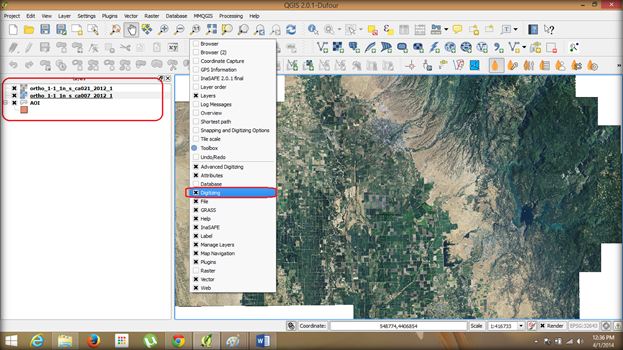
- Check if the Digitizing tools are available in the toolbar, if not right-click on the toolbar and check the ‘Digitizing’ option. The digitizing tools will be available now.

-
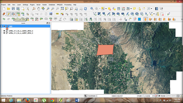
Select the AOI vector file in the Layer pane and click ‘Toggle Editing’ button.
-
All the tools which were inactive before becomes active, of these tools select ‘Add feature’ tool
and start digitizing the outer boundary of the provided AOI.
-
Zoom to the required level before digitizing. 1:10000 in this case.
-
Digitizing is done with each Left-click over the workspace providing a node or point of the polygon being formed, so by providing enough nodes the entire AOI is obtained as a vector layer.
-
After completing the entire outer boundary right-click to provide the feature ID and then click ‘Save edits’ button.

-
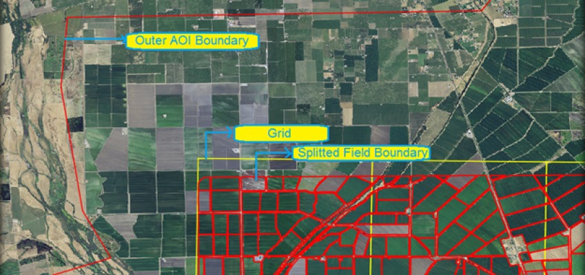
Before splitting the field boundaries from the AOI, create a Grid file of equal area over the AOI to make it easy to track the progress of digitizing. ‘Vector’ menu → ‘Research tools’ → ‘Vector grid’.
-
Provide the grid extent in case of raster image or select the AOI vector file as grid extent. Also provide the Grid parameters for the required size and save the file as Polygon providing destination and click ‘Ok’.

-
Open the grid vector layer and overlay it on top of the existing AOI shapefile.
-
For splitting the separate fields from the AOI click the ‘Split feature’ tool
and by similar way as of adding feature after each cut, provide the feature ID and after each cut a separate feature will be created.
-
Save edits after completing the segregation process and Click the Toggle editing button again to stop Editing.
The fields boundary will be created after the following process.

Correcting the Skewed field boundaries
-
Depending on the project scope the digitizing scale is maintained during the entire digitization process. Larger the scale greater the time required to digitize and better the accuracy.
-
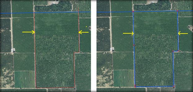
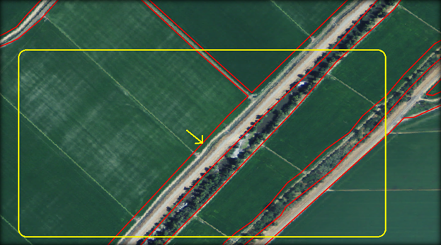
The boundaries appear to be accurate when viewed at 1:10000 scale whereas when viewed at an even greater scale of 1:5000 it appears to be offset and skewed.

-
After completing the digitization, if the requirement of scale changes to an even greater value, the digitized boundary appears to be offset to fields in the raster file.
- This is due to the scale variation. This can even occur while moving from low resolution imagery to high resolution imagery.
-
To correct this offset either ‘reshape feature’ tool or ‘Node tool’ can be used.
-
While using the Reshape feature tool
, just draw the corrected boundary on top of each field boundary which needs correction and the boundary of the feature changes to the reshaped boundary.

- The other option is the Node tool
by which the existing boundary nodes can be shifted to match the new requirement boundary.

Topology checker and Quality check
-
The digitization work always begins with digitizing the outer boundary of the AOI followed by splitting bigger blocks and finally cutting it further to match each separate field boundary.
-
This process is followed to reduce the amount of errors which can occur due to duplication and overlap of polygons.
-
Still there are a few topological errors which occur such as sliver polygons. These can be rectified by finding the errors by running the Topology checker plugin which is available QGIS plugin repository.
-
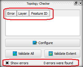
The Topology checker opens a function pane, click the configure button at the bottom to open a dialog box.
-
Here the layer to be checked along with the conditions that needs to checked is also mentioned.
-
After selecting each condition click the ‘Add rule’ button to add the rule for validation. Click ‘Ok’ after all the required conditions to close the dialog box and display the conditions in the function pane.


-
vClick the ‘Validate all’ to validate the whole vector file or ‘Validate extent’ to just validate the displayed extent.
-
After which the errors if any will be displayed on the function pane as well as on the map space.
-
Here it shows no existing errors and hence these can be delivered as a final product to the clients. If not the errors have to be corrected by eliminating duplicate polygons, snapping the fields which have gap.
This is how a digitization work has to be carried out to obtain a vector shapefile from the georeferenced raster images.